

HOW TO REPLACE THE FIXING FILM AND PRESSURE ROLLER FOR CANON IRA C5030, C5035, C5045, C5051 FIXING (FUSER) ASSEMBLY
Unsure how to replace the Canon fixing film and pressure roller? We'll show you step-by-step how to do this necessary maintenance to keep your unit running smoothly and keep your machine in top shape.
The following tutorial is for these models:
- Canon imageRunner Advance C5030, C5035, C5045, C5051
When Do You Need to replace the fixing film and pressure roller?
If you're getting error messages, this may indicate it's time to replace both the fixing film and pressure roller. Listed here are all the errors that indicate a problem:
- E001 0000 - Abnormal high temperature in Main Thermistor 1, 2
- E001 0001 - Abnormal high temperature in Sub Thermistor 1, 2
- E001 0003 - High temperature error detected by hardware
- E003 0000 - Error detected when the Heater is ON
- E003 0001 - Abnormal detection during paper feeding
- E003 0002 - Abnormal low temperature when the Heater is ON
- E003 0004 - Timeout at start-up
- E004 0000 - Thermistor disconnection detection error
- E004 0001 - Error in detection of welding with fixing relay
- E009 0000 - Error in engagement
- E009 0001 - Error in disengagement
- E009 0002 - Pressure error (it is highly possible that grease is scattered on the surface of the cam.)
Step-by-Step Guide: Replacing the Fixing Film and Pressure Roller
Prior to starting, it is imperative to remember power off the device and disconnect from its power source at the back.
This step-by-step tutorial will further break down the steps to remove and replace the Fixing Film and Pressure Roller for Fuser Unit. Let’s begin!
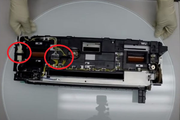
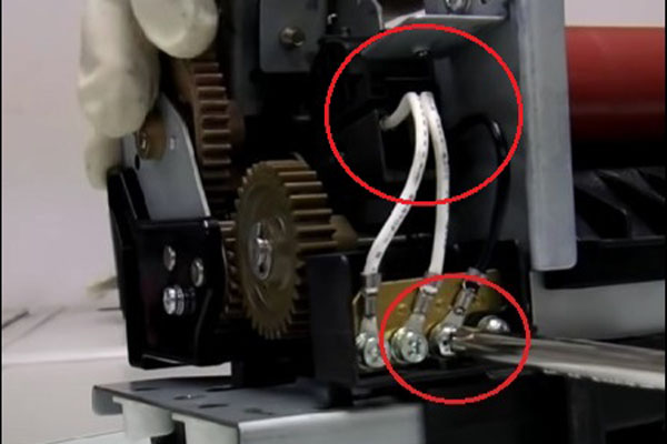
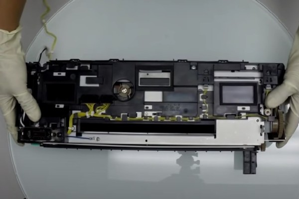
Step One: Remove Fuser Unit Harness
Start by unplugging all the harnesses on top of the Fixing (Fuser) Unit. Then, carefully remove any wires wrapped around the unit.

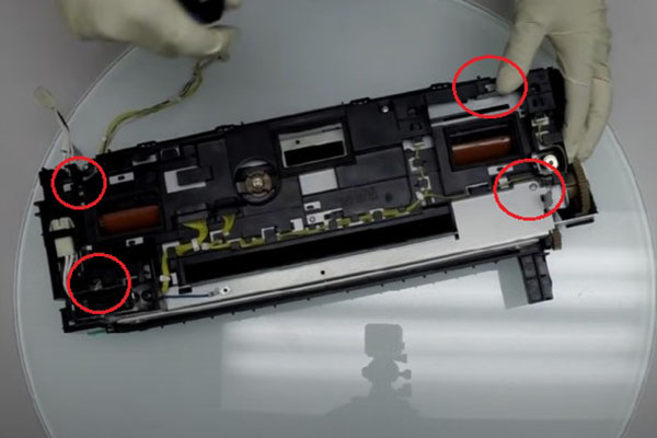
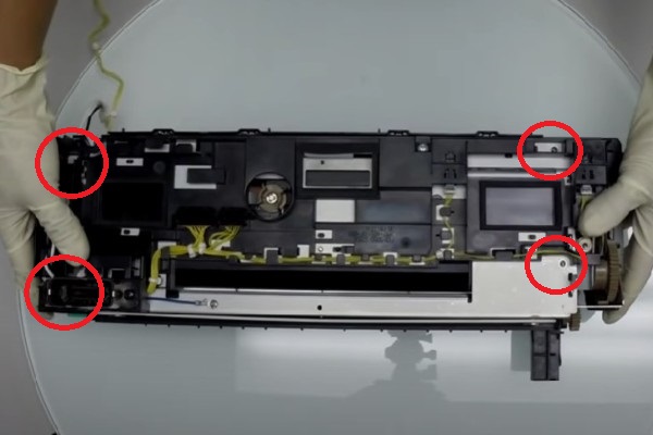
Step Two: Remove Top Cover Screws
Remove the four screws securing the top cover. Gently lift the cover upwards, removing the cover from the unit.
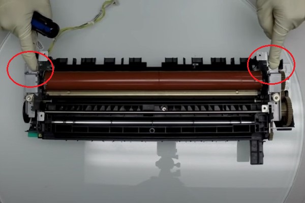
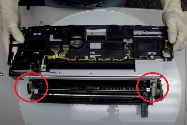
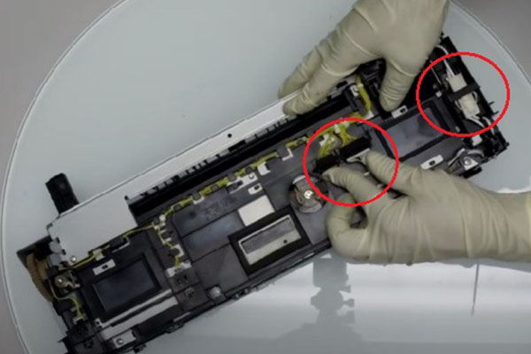
Step Three: Release Pressure Relief Brackets
Release the two metal pressure relief brackets by removing the screws found on the sides. These brackets hold the fixing film roller in place.
Step Four: Unplug Fuser Unit Connector
Unplug the black connector of the fixing film assembly and run the wires to the middle of the fixing assembly.
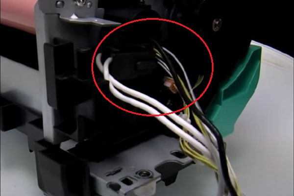
Step Five: Unplugging Connector
Turn the unit around to disconnect the rest of the harness. To do this, find the screw holding the ground cable and unscrew it followed by unplugging the other black connector.
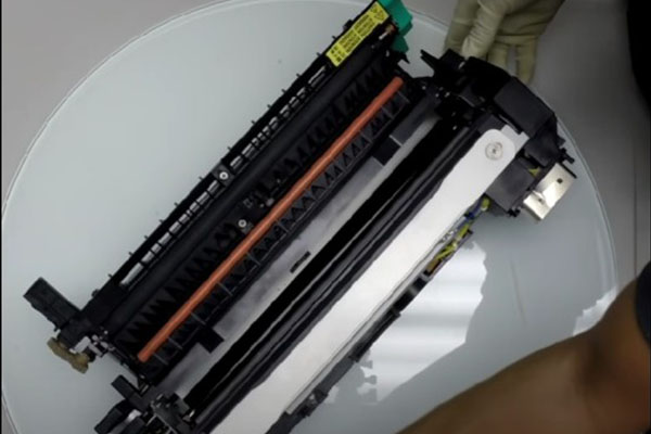
Step Six: Remove Fixing Film
Once all the connectors and cables have been released, lift the fixing film assembly vertically up and out of the fuser unit.
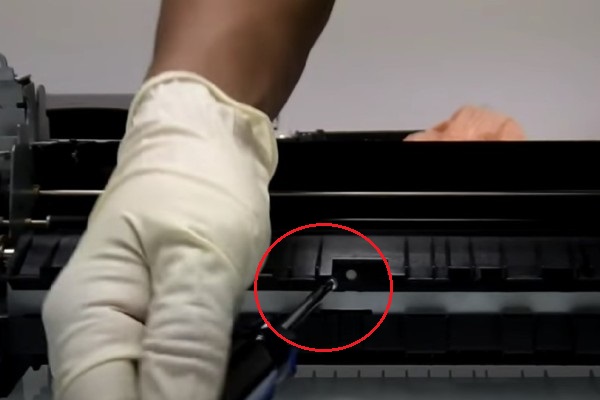
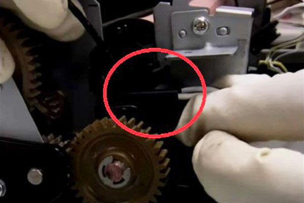
Step Seven: Remove Fixing Guide Screw
Remove the one screw found in the front of the fixing entrance guide.
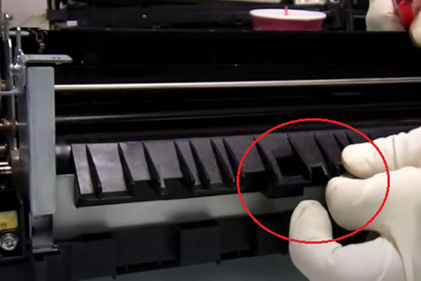
Step Eight: Remove Fixing Entrance Guide
Then, release the security tab by loosening and sliding slightly to the right. Remove the fixing entrance guide by gently lifting upwards away from the printer.
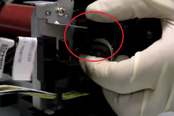
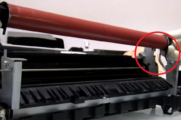
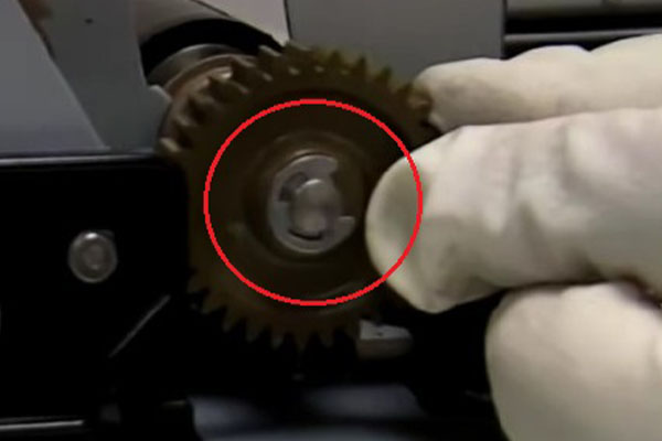
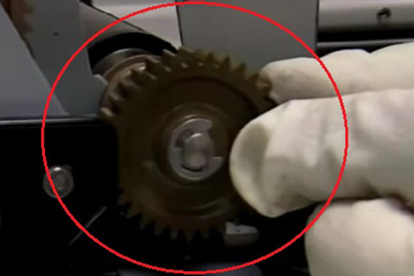
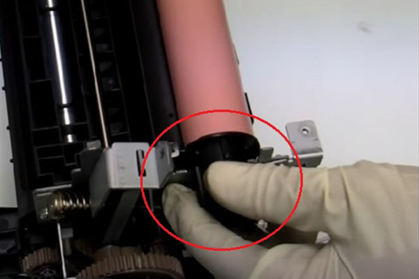
Step Nine: Remove C-Clip
Next, Remove the c-clip on the gear found on the side of the pressure roller. Do this by applying gentle downward pressure on to the c-clip, removing it from the bearing.
Step Ten: Release Pressure Roller
Push the plastic bearings aside to release the roller and lift vertically to remove from the unit. Set the plastic barring aide for later reassembly.
Step Eleven: Replace Bearings
To begin reassembly, start by placing the two bearings on both ends of the new gear assembly.
Step Twelve: Replace Pressure Roller
Align the gear assembly from the top looking down and then insert downward back into the unit. Make sure to lock everything in place by reattaching the c-clip to the gear.
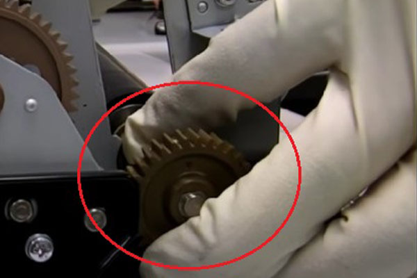
Step Thirteen: Align the Pressure Roller
Rotate the gear to check that the assembly runs smoothly. Proper alignment is crucial for the fuser unit to function correctly.
Step Fourteen: Replacing Film Assembly - Part A
Once completed, begin inserting the guide into the film assembly. You will need to reuse the guide that you have.
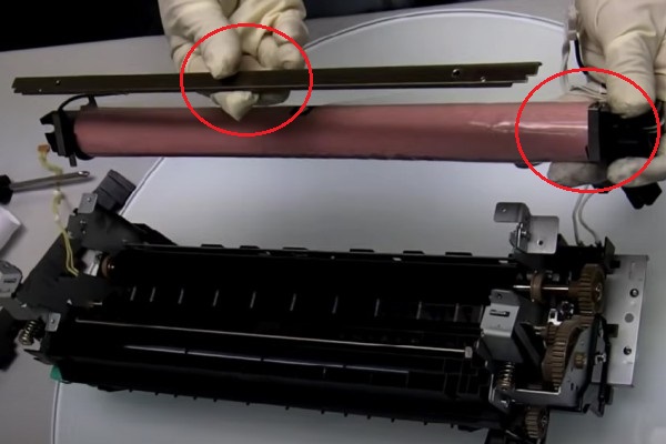
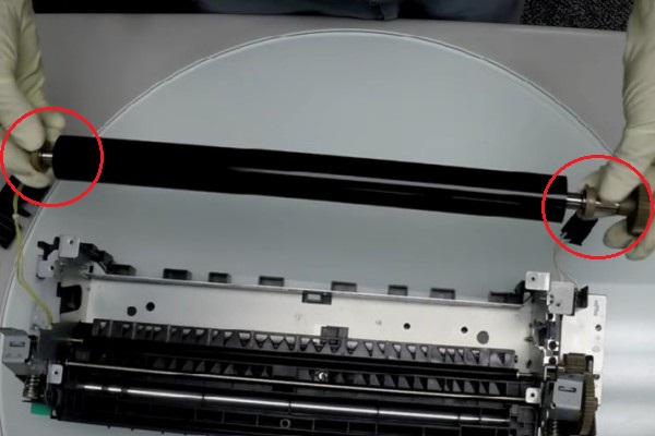
Step Fifteen: Replacing Film Assembly - Part B
Start by removing the two metal clips found on both ends of the film assembly.
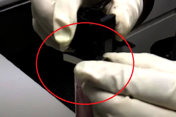
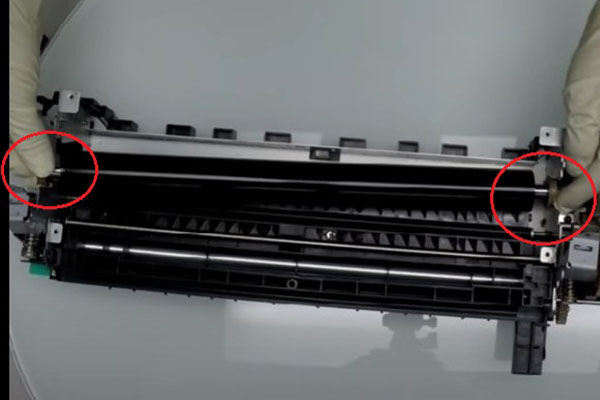
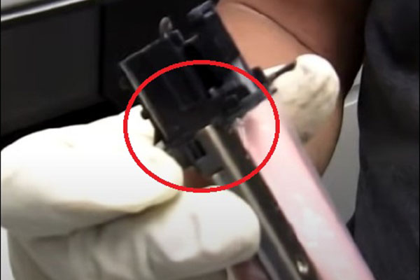
Step Sixteen: Replacing Film Assembly - Part C
Insert the guide into the notches found on both sides of the film assembly where the clips previously were. Lock the guide into position by re-attaching the metal clips on both ends.
Step Seventeen: Replacing Film Assembly - Part D
Before inserting the film assembly back into place, remove the protective plastic. Inserting downwards, ensure the notches and guides are aligned properly with the fuser unit frame.
Step Eighteen: Reconnect Film Assembly
Reconnect the black connector and ensure all cables are properly secured and routed along both sides of the fuser unit.
Step Nineteen: Lock Pressure Release Brackets
Lock the pressure release brackets on both sides back into place by applying gentle downward pressure on the bracket and reinsert the screw. Repeat this process with both pressure relief brackets.
Step Twenty: Replace Entrance Guide
Reinstall the entrance guide by aligning the plastic notches with the metal frame of the unit. After placing the guide into the aligned notches, slide slightly to the left, locking it into place. Then secure the previously removed screw.
Step Twenty-One: Replace Fuser Top Cover
Go through and inspect that all connections harness layout before placing the top cover back on. Once inspected, align the cover vertically above the unit and line up the four medal notches. When aligned, press downward on the cover placing it back onto the fuser. You should be able to audibly hear and feel when the cover snaps into place, but this may take some adjustments
Step Twenty-Two: Replace Top Cover Screws
Once locked into place, re-insert the 4 screws securing the top cover into place.
Step Twenty-Three: Reconnect Fuser Harness
Finally, reconnect all the harnesses. Ensure they are correctly routed and secured along the plastic cover.
Step Twenty-Four: Inspect Fuser Unit
Finally, perform a final check by rotating the gears and ensuring nothing is stuck or grinding.
Order Your Replacement Parts Today!
Congratulations! You’ve learned how to successfully and adequately replace and change the Fixing Film and Pressure Roller from your Canon Fixing (Fuser) Unit. Great job!
- FM3-5950-000, FM3-5950-010, FM3-5950-000-AM, FM3-5950-010-AM - Canon – Fixing Film Assembly
- FC0-5061-000, FC8-4906-000 - Canon - Pressure Roller
- FM3-5947-000, FM3-5947-010, FM4-8420-000, FM4-8420-010 - Canon IRA C5030 Fixing (Fuser) Assembly
Follow Us on YouTube for More Tutorials
Thank you for completing this step-by-step tutorial! We hope you found it useful. Remember to stay connected with us by following our YouTube channel and subscribing for more important content. We would love to hear from you, so please leave a comment.
Click here to view Item, Inc. YouTube channel.
Need More Help?
If you need more assistance, contact us. For sales, repair, or unsure about a part, call us, use our chat feature, or email us. We're here to help in any way!