

How to replace fuser unit for Lexmark E260, E460, X264, X363
If your Lexmark machine is experiencing some problems and showing error messages, it may be time to replace the fuser. In this article, we will do a deep dive into when it is time to replace your fuser and a helpful step-by-step guide to walk you through the process easily and quickly.
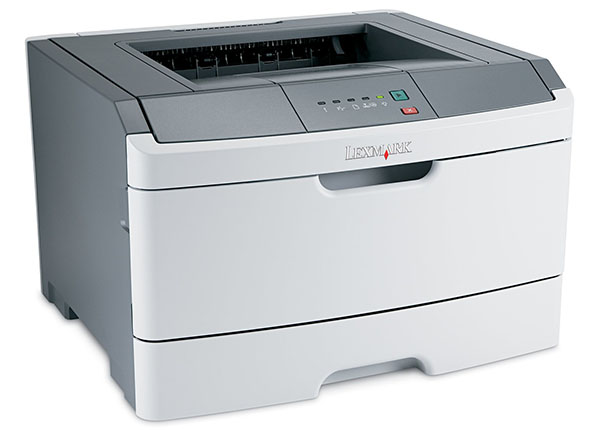
The following tutorial is for these models:
- Lexmark E260, E360, E460, E462, ES460, X264, X363, X364, X463, X464, X466, XS463
When Do You Need to replace the fuser?
If you encounter an error code between 920 and 925, it will be identified as a fuser error. However, when dealing with the E260 model, checking for a fuser error requires initially noticing a service error. When all the lights on the front panel start flashing, take action by double-clicking the green arrow button to unveil the secondary error code. If only the second light and arrow key are flashing, it signifies a toner sensor, fuser, or fan error. If this occurs, double-click the arrow button once more to reveal the specific error. Listed here are all the errors that indicate a problem with the fuser:
- 920.xx - Fuser below temperature when printing.
- 921.xx - Fuser below standby temperature at idle.
- 922.xx - Fuser failed to reach standby temperature.
- 923.xx - Fuser too hot during printing or idle.
- 924.xx - Open circuit in thermistor path.
- 925.xx - Incorrect fuser.
- 926.xx - Service fuser error.
Step-by-Step Guide: Replacing the fuser
Prior to starting, it is imperative to remember power off the device and disconnect from its power source at the back.
This step-by-step tutorial will further break down the steps to remove and replace Lexmark fuser. It will take approximately 30 minutes to replace the fuser, and you'll need a Phillips head screwdriver for the task. Let’s begin!
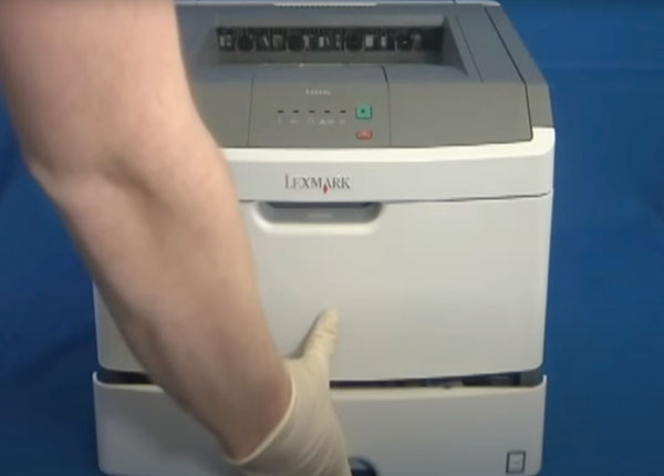
Step One: Remove Paper Tray
To begin, remove the paper tray from your Lexmark printer as the initial step.

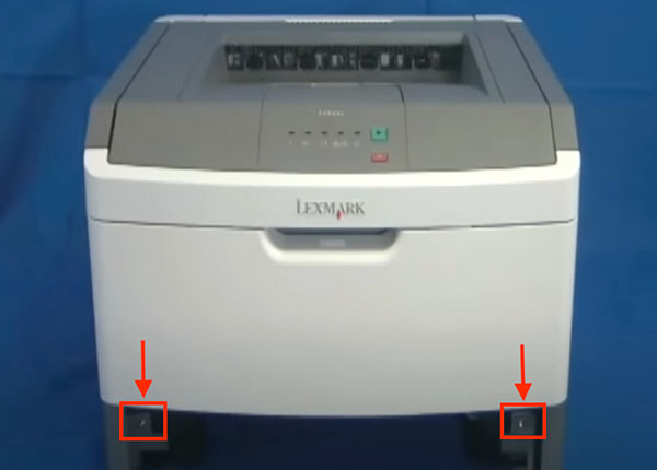
Step Two: Remove Cover Screws
After taking out the paper tray, proceed by removing the two screws located on the side covers.
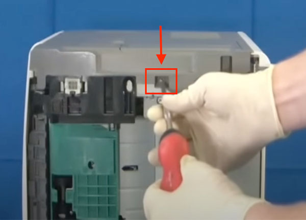
Step Three: Remove Right Side Cover Screw
Turn the printer to its side and remove the screw.
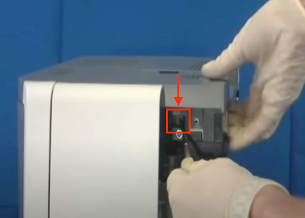
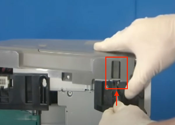
Step Four: Remove Right Side Cover - First tab
Begin by pressing the tab at the front of the printer to initiate the removal of the right side cover.
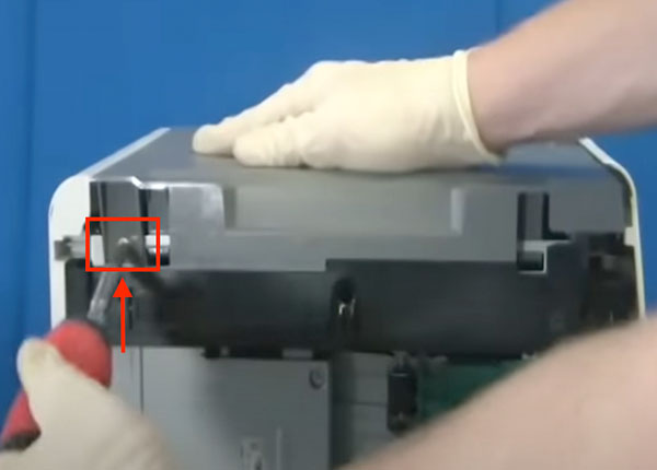
Step Five: Remove Right Side Cover - Second tab
Then, proceed by pushing upward on the tab situated at the bottom of the printer. Carefully slide the cover upwards toward the top of the machine to remove it.
Step Six: Remove Left Side Cover Screw
Next, position the printer on the opposite side and proceed to remove the screw.
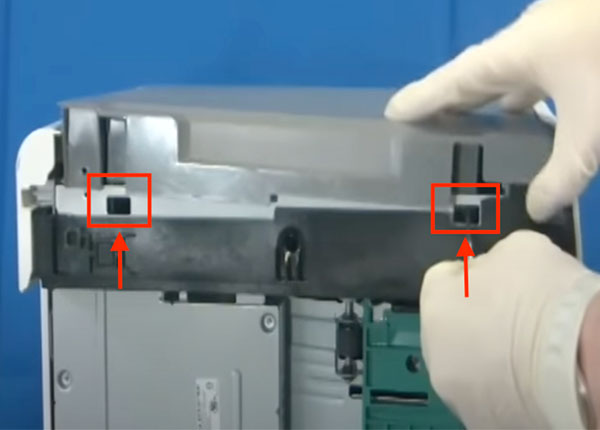
Step Seven: Remove Left Side Cover
Push down on the two tabs and lift the left cover outward and upward to remove it.
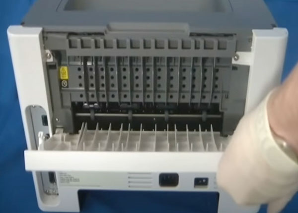
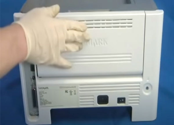
Step Eight: Remove the Rear Door
Stand the machine upright and open the rear door. Then, firmly pull the door straight out to remove it.
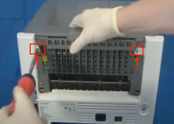
Step Nine: Remove the Rear Cover
Take out the two screws securing the rear cover, then proceed to remove the rear cover itself.
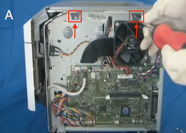
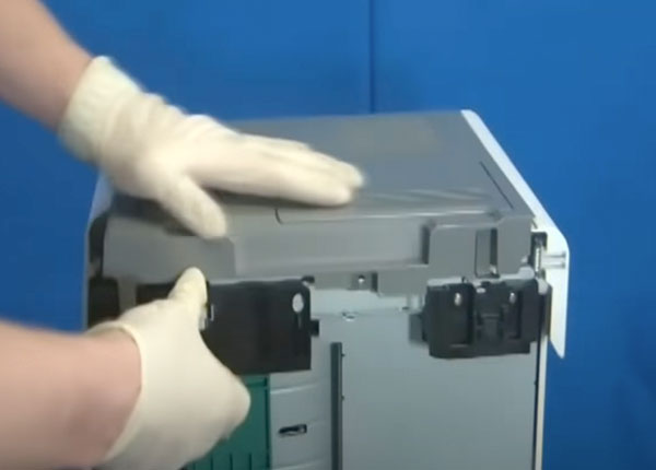
Step Ten: Remove Top Cover - Side A
To detach the top cover, begin by removing two screws from one side
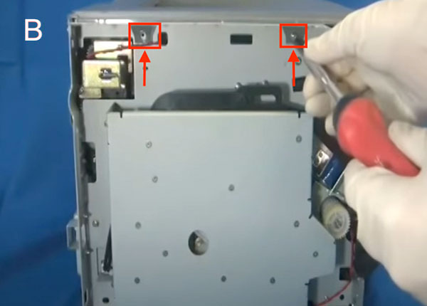
Step Eleven: Remove Top Cover - Side B
Perform the same steps on the other side by removing the respective screws before lifting the top cover off.
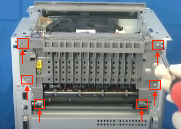
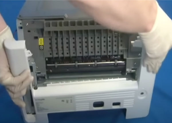
Step Twelve: Remove Rear Exit Guide Assembly Screws
First, the rear exit guide assembly requires the removal of a total of six screws.
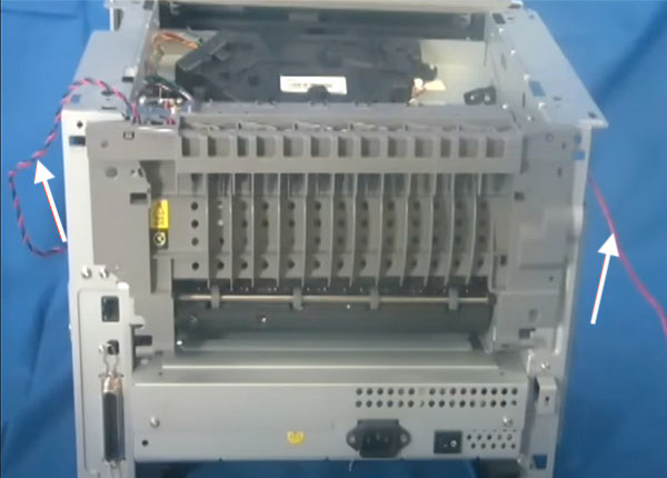
Step Thirteen: Remove Rear Exit Guide Assembly Cables
Then, unplug the three cables that connect to the fuser and rear exit guide on the main board.

Step Fourteen: Remove Rear Exit Guide Assembly
Following that, carefully remove the exit guide by unthreading the two cables connected to it.
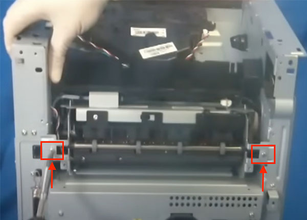
Step Fifteen: Remove Fuser Screws
Take out the two screws securing the fuser, then gently pull the fuser outwards.
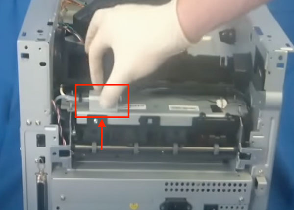
Step Sixteen: Remove Fuser Plate
Push down on the metal plate and lift it to remove it from its place.
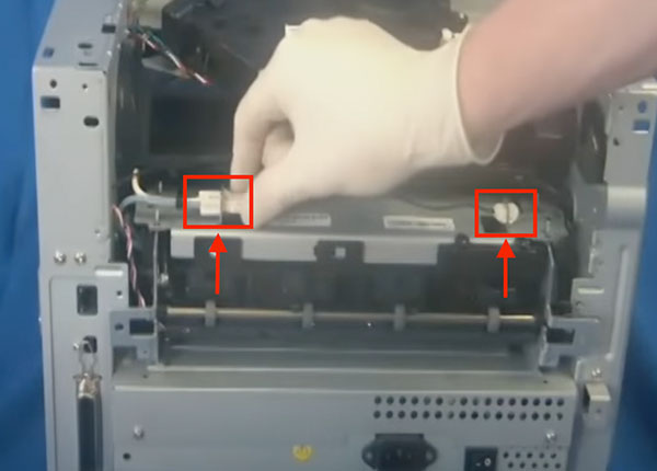
Step Seventeen: Remove Fuser
Carefully disconnect the two cables, ensuring you unthread them properly, before removing the fuser.
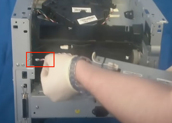
Step Eighteen: Installing New Fuser
Install the new fuser by sliding the cable in first.
Step Nineteen: Installing New Fuser
Connect the two cables and reattach the metal plate securely. Secure the fuser by fastening the two screws back into place as shown in Step 15.
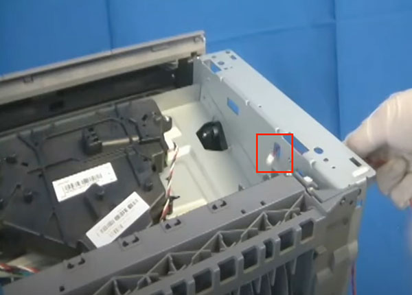
Step Twenty: Installing Exit Guide Assembly - Substep A
When you install the exit guide, make sure you thread the red cable correctly through the machine.
Step Twenty-one: Installing Exit Guide Assembly - Substep B
Fasten the exit assembly by securing all six screws back into place.
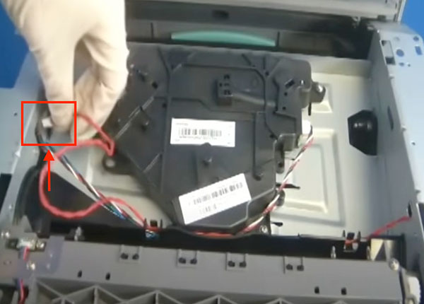
Step Twenty-Two: Installing Exit Guide Assembly - Substep C
Complete the process by properly threading the red cable from the exit assembly.
Step Twenty-Three: Installing Exit Guide Assembly - Substep D
Connect the three cables securely back into the main board.
Step Twenty-Four: Install Top Cover
Securely reattach the top cover and fasten the four screws on both sides.
Step Twenty-Five: Install Rear Cover
Reattach the rear cover and tighten the two screws securely.
Step Twenty-Six: Install Rear Door
Reattach and close the rear door.
Step Twenty-Seven: Install Side Covers
Reattach each side cover, starting from the top side, and secure them by screwing in the respective side screws as shown in Step 6 & 7. Repeat this step for the other side.
Step Twenty-Eight: Fastening Side Cover Screws
At the front of the printer, fasten the two remaining screws securely.
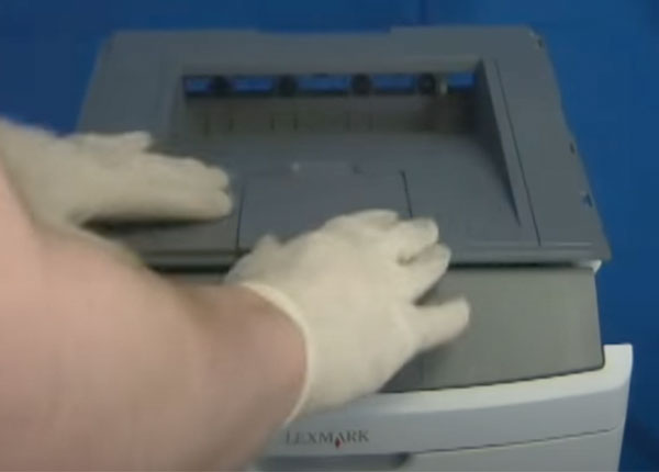
Step Twenty-Nine: Replacing the Tray
Finally, complete the process by inserting paper tray.
Order Your Replacement Parts Today!
Congratulations! You’ve learned how to successfully and adequately replace and change your fuser for your Lexmark E260. Great job!
- 40X5344 - Lexmark Fuser Assembly, 110V
Follow Us on YouTube for More Tutorials
Thank you for completing this step-by-step tutorial! We hope you found it useful. Remember to stay connected with us by following our YouTube channel and subscribing for more important content. We would love to hear from you, so please leave a comment.
Click here to view Item, Inc. YouTube channel.
Need More Help?
If you need more assistance, contact us. For sales, repair, or unsure about a part, call us, use our chat feature, or email us. We're here to help in any way!